What is a Terminal Unit?
Introduction to Terminal Units
The control of air distribution in modern buildings is typically accomplished by the use of air terminal units. A terminal unit is a device that is used to regulate the volume of conditioned primary air from the central air handler to the occupied space. When establishing the required air volume for each space, one should consider both the thermal conditions, as well as fresh air requirements based on occupancy.
A terminal unit controls the primary air volume to a zone through the use of a primary air valve that contains an inlet, damper, and controller. This control of primary air to the occupied space, in communication with the thermostat measuring real-time temperature in the occupied space, allows the desired temperature set-point to be maintained.
Terminal unit selection and application is therefore a critical component of the overall HVAC building system, and will have a direct impact on both the occupant comfort, as well as perceived sound levels within the built and furnished occupied space.
An ideal terminal unit specification will clearly specify the maximum allowed discharge and radiated sound power levels by octave band.
-------------------------------------------
Terminal Unit Types
Terminal units are available in many configurations to suit a variety of performance requirements:
- Single Duct
- Parallel Fan Powered
- Series Fan Powered
- Dual Duct
- Retrofit
Back to Top
-------------------------------------------
Single Duct
A single duct terminal unit, also commonly referred to as a VAV, is one of the most simple and cost effective devices capable of controlling and delivering airflow to a zone. A single duct box typically has a round inlet where the flow sensor and damper is mounted, followed by a rectangular casing that incorporates a liner with acoustic and thermal benefits. There are many types of liners available – the most typical being fibrous duct liner, complying with ASTM C 1071.
VAV terminal units use direct digital controls (DDC) that operate as either pressure-dependent or pressure-independent:
- Pressure-dependent controls will actuate the terminal unit damper in response to zone temperature, but the total airflow leaving the device will be dependent on pressure fluctuations in the ductwork.
- Pressure-independent controls rely on a signal from the flow sensor in order to compensate for pressure fluctuations in the ductwork, while still ensuring the desired airflow is delivered.
In terms of airflow, these devices may be constant air volume or variable air volume – the choice of which depends on many factors, including room occupancy, and how much the load in the zone may fluctuate.
Note: the choice of a constant volume approach vs variable volume approach may impact the operation of the central air handler.
All performance for single duct units are based on tests conducted in accordance with the current edition of ASHRAE 130.
Constant Volume Single Duct
Constant volume operation is generally desirable if the load in the intended zone does not fluctuate. This type of air volume strategy is often employed with single speed air handlers without variable frequency drive (VFD) capability.
A single duct terminal with constant volume operation may or may not have an actuator, flow sensor, and controls. If the unit does not have an actuator, it is typically supplied with a manually locking quadrant that allows the damper blade to be locked into a single position.
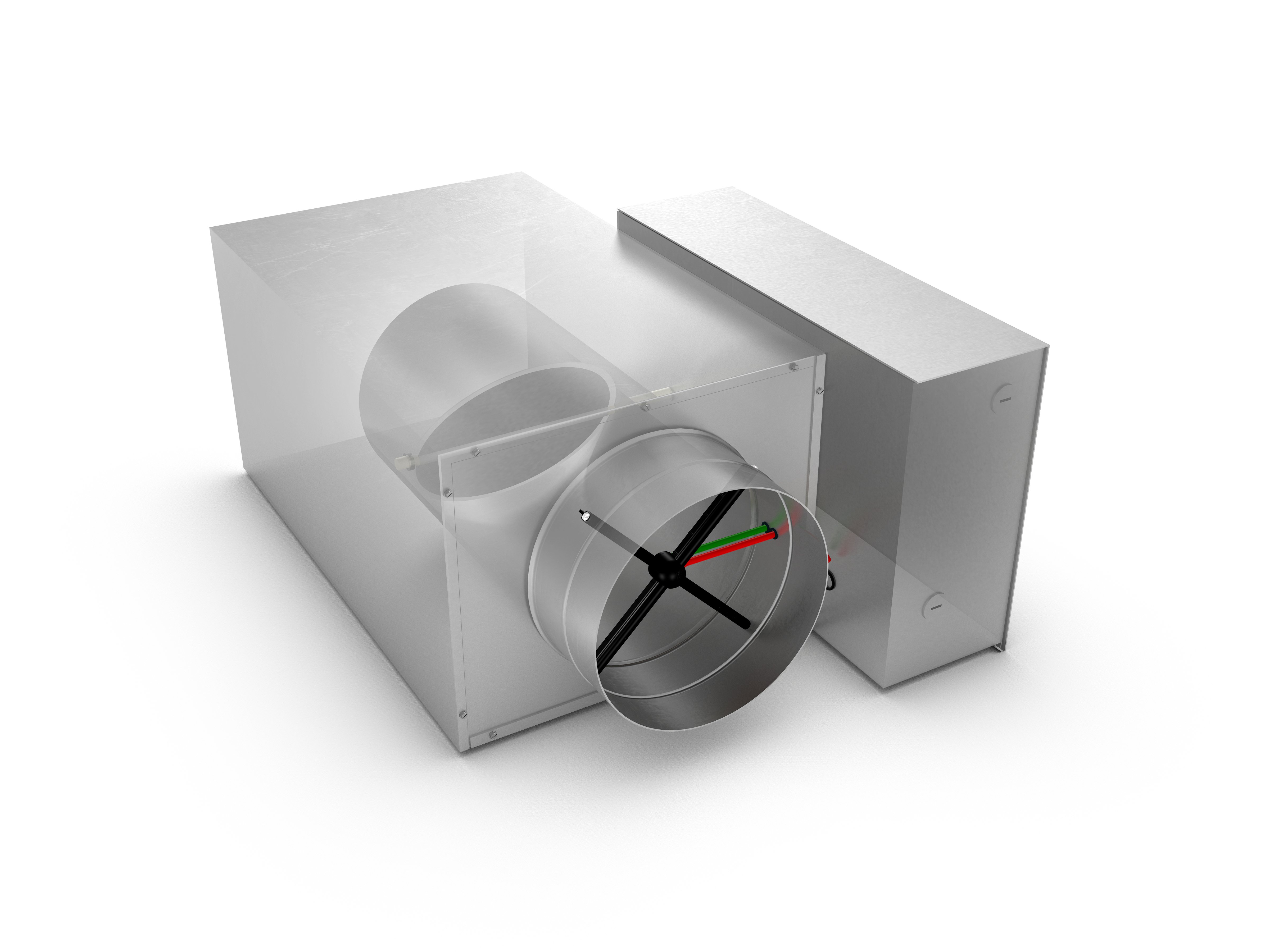
Variable Volume Single Duct
Variable volume operation is desirable if the occupancy and/or load in the intended zone is expected to fluctuate. To handle the fluctuating system air volumes, central air handlers must either have VFD capability, or there needs to be a bypass relief to the return of the air handler. Variable volume operation requires the DDC package to communicate with the actuator on the damper shaft to modulate the amount of airflow leaving the terminal unit.
With the increased focus within the industry on energy efficiency, variable volume control strategies with pressure independent capability are the basis of design for many consulting Engineers.
Back to Top
-------------------------------------------
Fan Powered Terminal Units
A fan powered terminal unit (FPTU), commonly referred to as a fan powered box (FPB), is an air terminal unit which contains both a primary air inlet, as well as a local motor and blower assembly. Traditionally, a Permanent Split Capacitor (PSC) type motor was employed in these air terminal units and was capable of local adjustment only. In the present day, most Engineers are designing these boxes with Electronically Commutated Motors (ECMs), due to both their superior energy efficiency, as well as their ability to modulate output based on a 0-10 V DC control signal.
Fan powered terminals generally come in either a parallel or series arrangement, determined by the location of the fan in the assembly.
Parallel or Intermittent Fan Powered Terminal
The basic parallel fan powered terminal - sometimes referred to as intermittent - consists of:
- Air inlet assembly similar to a single duct
- Blower/motor assembly
- Divider panel between the air inlet and motor section, with a back-draft damper at the fan outlet
- Outer lined casing
- Return air opening
- High voltage connection
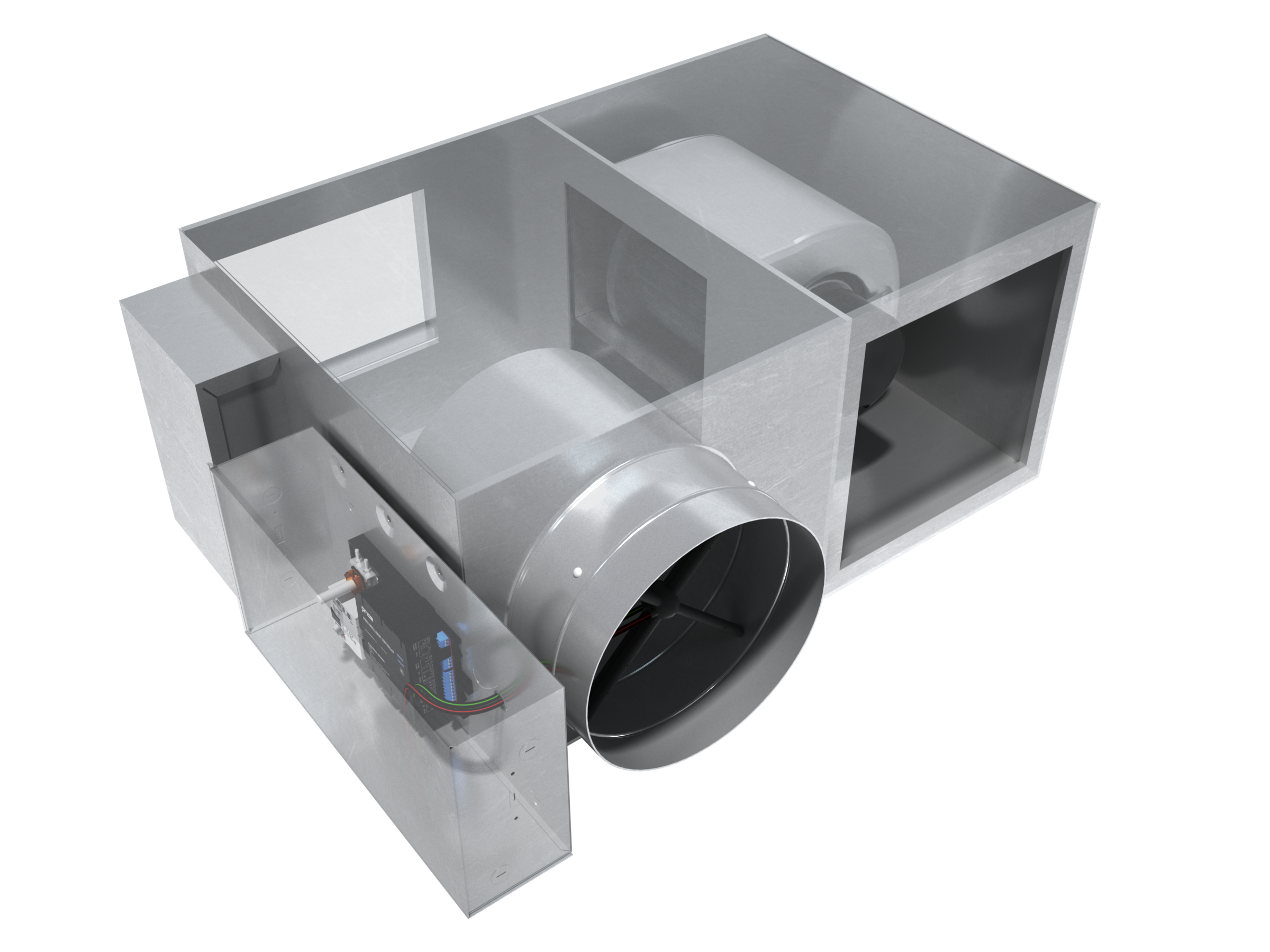
The discharge air from the parallel fan powered terminal is a combination of primary air from the central air handler, and fan air volume pulled from the surrounding plenum.
The traditional DDC sequence of operation for this FPTU arrangement is for the primary air valve to modulate between maximum and minimum cooling setpoints, with the fan only coming on when there is a call for heat. If this sequence of operation is being employed, the impact of the intermittent fan operation should be considered on the perceivable acoustics in the occupied space. Some engineers have started to sequence the fan to continually run at a low speed, blending plenum air with colder primary temperatures.
Back to Top
------------------------------------------
Series Fan Powered
Series or Constant Volume Terminal Unit
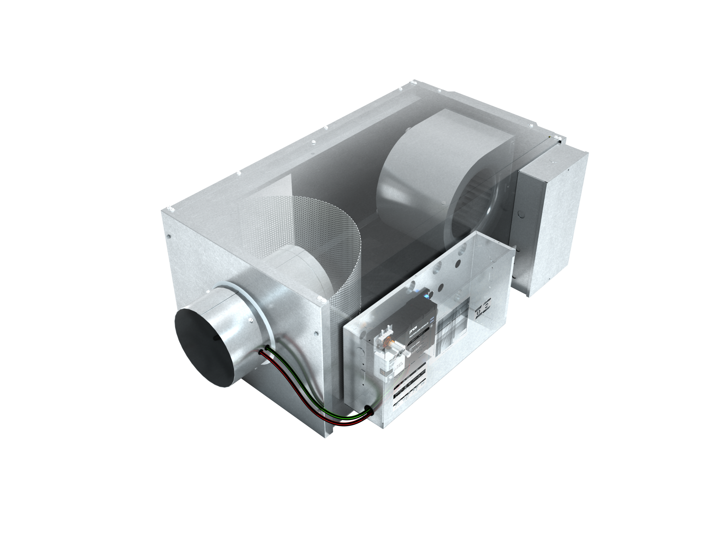
The basic series fan powered terminal - sometimes referred to as constant volume or constant fan - consists of:
- Air inlet assembly similar to a single duct
- Blower/motor assembly
- Outer lined casing
- Return air opening
- High voltage connection
All discharge air from the series fan powered terminal is driven by, and dependent on, the blower/motor assembly located on the discharge of this terminal unit. This discharge air is a mixture of supply air from the air inlet assembly and the return air opening. Whatever air volume the fan does not get through the air inlet assembly, it will pull from the plenum space through the return.
The traditional DDC sequence of operation for this FPTU arrangement has the fan running a constant volume, hence why some people refer to these units as ‘constant volume’ terminal units. However, this label is no longer accurate nor appropriate: with ECM technology becoming the default for fan powered assemblies, the fan may be modulated according to fluctuating demand in the occupied space.
Back to Top
------------------------------------------
Dedicated Outdoor Air Systems
What is a DOAS System?
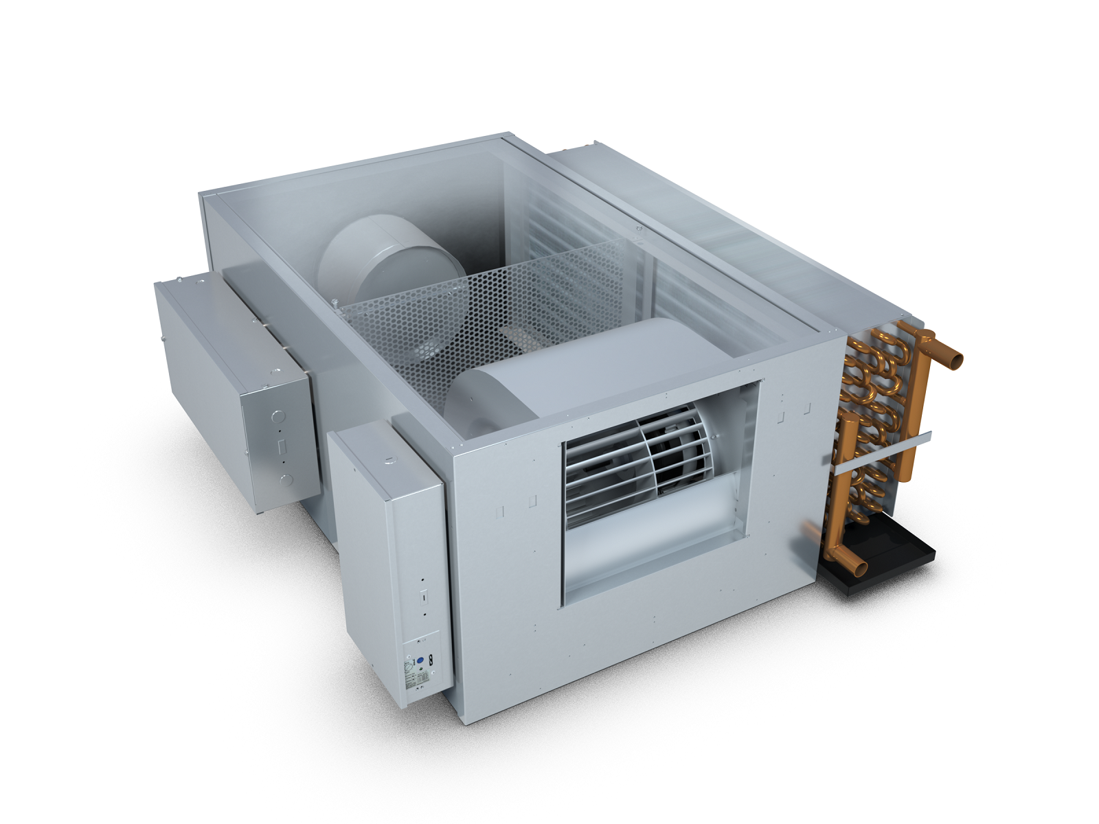
Dedicated Outdoor Air Systems (DOAS) leverage the energy storage capability of water, along with the core belief that one should only condition the minimum amount of fresh air required for any space, based on the occupancy and latent cooling requirements. As a result, a DOAS air handler conditions lower volumes of fresh air to handle all the latent cooling needs in the bulding, while all sensible cooling is done locally through a sensible cooling coil near each zone. In order to deliver and control the individualized comfort of each space, a local fan powered terminal unit in a series arrangement with an integral sensible cooling coil is commonly utilized.
DOAS offers energy saving benefits which complement the design goals of Green/LEED buildings. DOAS is gaining significant traction in the HVAC market because of its ability to offer superior ventilation performance, occupant thermal comfort, and enhanced energy savings when compared to traditional VAV systems.
Series Fan Powered with DOAS
A series FPTU with a sensible cooling coil offers one of the most versatile arrangements of achieving zone control in a DOAS system. The conditioned fresh air is brought into the primary air valve, and is controlled via the damper in response to either an occupancy thermostat, or CO2 measuring thermostat. The sensible cooling coil handles all sensible cooling in the intended zone.
The fan in the series arrangement compensates for all downstream static pressure losses, such that the DOAS air handler may be further downsized, and is not needed to overcome the pressure drop of the sensible cooling coil, nor the pressure losses of the air outlets in the space, nor drive any sort of return air induction. During night-setback, the local FPTU can maintain thermal conditions in the space, allowing the air handler to be turned off.
Due to the sensible nature of the cooling coil, the entering water temperature (EWT) is often quite high: typically in the range of 55-59°F. Psychrometrics are key - the EWT must be above the dew point of the air passing over the coil. This has a significant impact on the design of the unit, specifically in the size of the sensible cooling coil, which is required to be very large in order to offset the lessened thermal gradient between the two heat transfer fluids.
It is often desirable to place the series FPTU outside of sound sensitive spaces with supply and return ducted in, resulting in superior acoustic properties in occupied zones. DOAS terminal units can be provided with a factory installed silencer that further reduce perceived sound levels.
DOAS series FPTU solutions are easy to install for the contractor, have quiet operation, and rely on fewer pieces of equipment when compared to other DOAS systems.
Back to Top
-------------------------------------------
Dual Duct
Non-Mixing Dual Duct
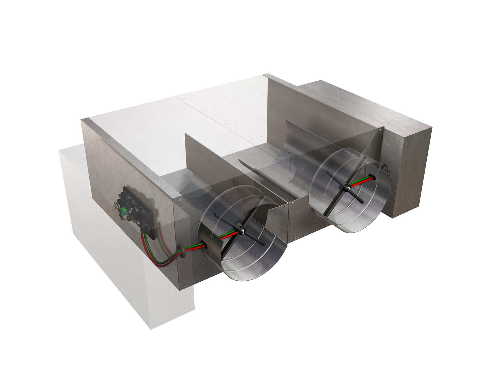
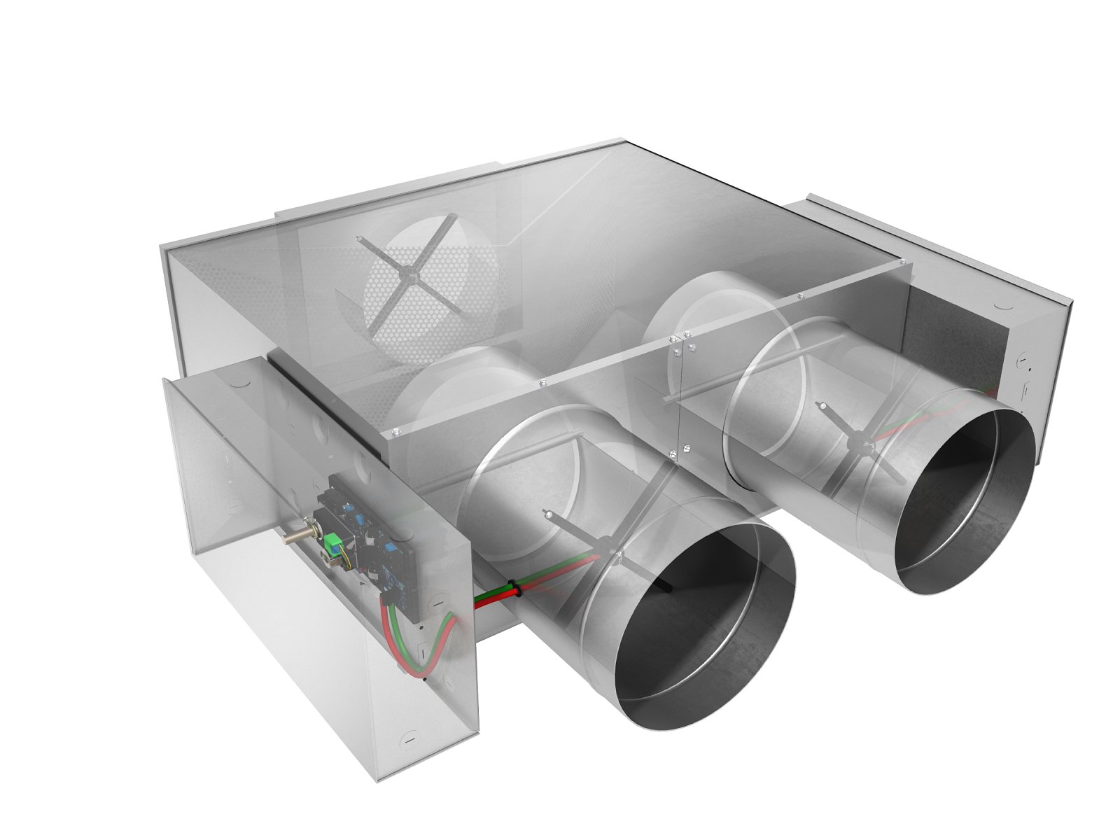
A non-mixing dual duct terminal is essentially two single ducts fastened together with one common discharge opening. The inlets are connected to two of the following: cold air, warm air, or fresh air. The non-mixing type of dual duct terminal has the potential to have thermally stratified discharge air and should have a minimum of three to five equivalent diameters of discharge duct to allow the different air temperatures to mix.
Non-mixing dual ducts are commonly used for exterior zones in buildings where the use of auxiliary reheat (such as water coils) is not desired and where a zero minimum flow is acceptable during changeover from heating to cooling.
Mixing Dual Duct
Back to Top
------------------------------------------
Water Coils
Water Coils (Heat Exchangers)
The most common water heat exchanger design utilized in terminal unit applications is the fin and tube construction. They generally consist of rows of smooth copper tubes mechanically expanded into thin aluminum ‘fins’, which increase the effective heat transfer area of the device. For applications utilizing corrosive air sources, such as an air handler pulling in salty coastal air, a copper tube/copper fin arrangement, or water coil with protective coating, would be more desirable.
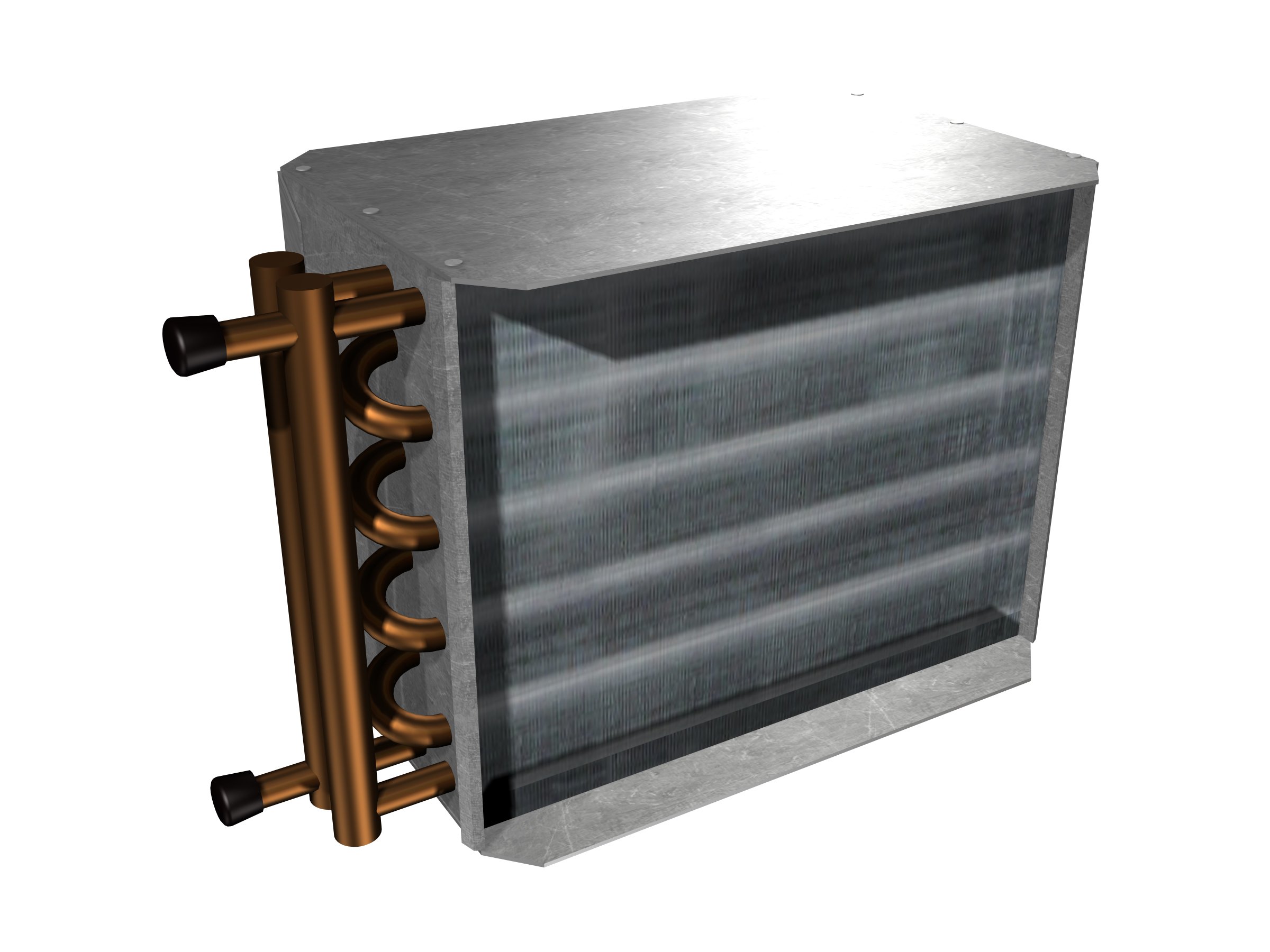
For terminal unit applications, most manufacturers participate in the AHRI 410 certification program. This program is generally regarded as a best practice, to ensure that software used to estimate coil performance is validated against actual 3rd party lab testing. These audits are performed annually.
Water coils require a valve package, or piping package, to control the fluid flow through the device. Though sometimes field furnished and installed, these valve packages are often offered as a factory assembled option, with components as required for the application.
Back To Top
-------------------------------------------
Electric Coils
Electric Reheat Coils for Terminal Units
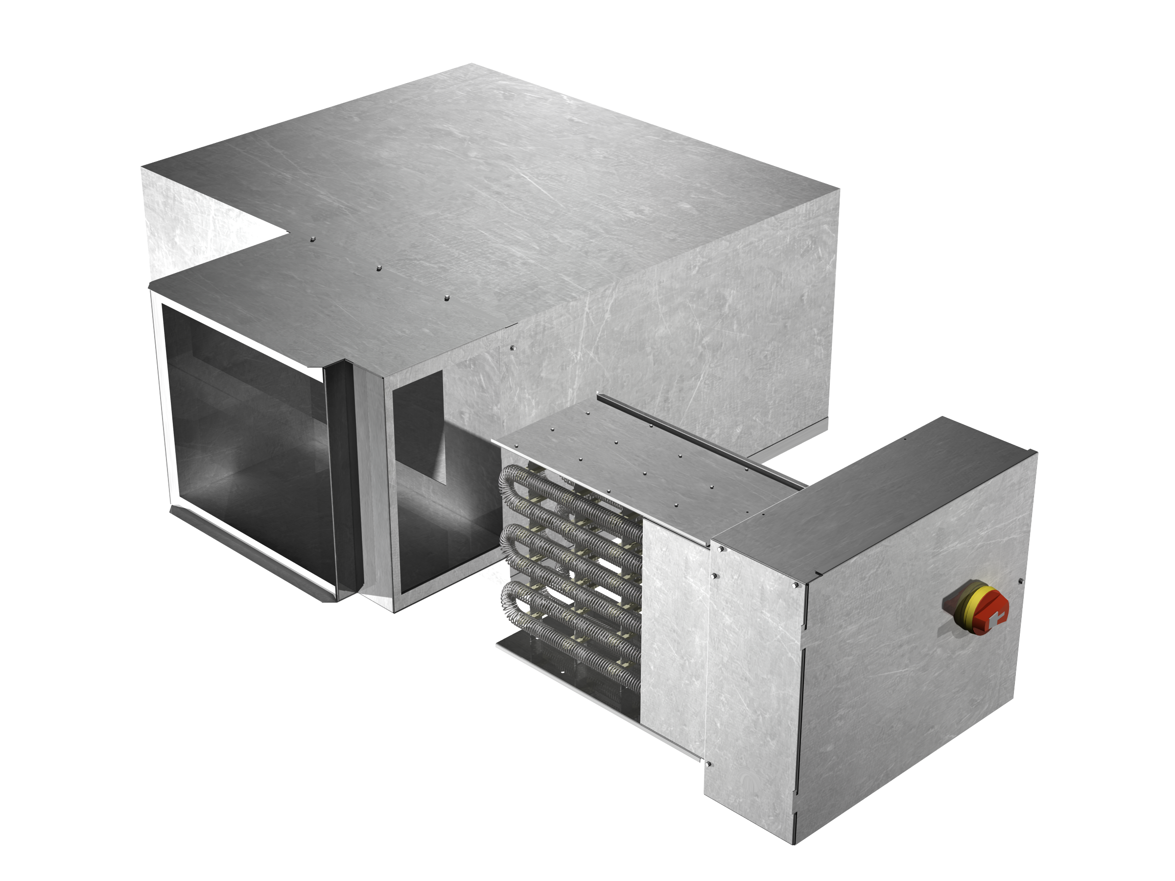
Electric coils may be used as sources of heat on most types of terminal units, and are typically located at the discharge of the terminal. They operate based on a line voltage passing through a resistive load (ie. the element rack comprised of coiled wire), which thereby creates heat. Our industry generally assumes electric coils to be 100% efficient. Because these devices require line voltage to operate, they are UL certified for the intended application. Be careful about deviating from the manufacturer’s installation label on their heater – electric coils are generally designed to be installed horizontal and level, though some manufacturers offer field flip-ability for the sake of opposite side handing.
Most design guides recommend that discharge air temperatures do not exceed 120°F. The minimum airflow requirement for electric coils is typically 70 cfm/kW of capacity. This is the minimum air mass required to adequately strip the elements of heat. To ensure adequate mixing in the space, it is generally desirable to limit the heated air to 15F above the ceiling temperature.
There are a few different ways to control the electric heater. The most cost effective method is to use a staged solution, which effectively breaks up the entire electric coil kW into discrete amounts. A single stage heater will energize the entire electric coil on a call for heating, whereas a 2-stage heater will typically energize half the coil kW on the initial call for heat, and increase proportional to time. 3-stages is typically considered the max number of stages offered. While cost-effective, staged heating typically offers the least control over the heated air entering the space.
The more common strategy of controlling the electric coil is a modulating signal type, commonly referred to a Silicon Controlled Rectifier (SCR). SCR control typically results in the entire heater kW being pulsed according to a duty cycle as defined by the call for heat signal coming from the terminal unit controller. SCR heat strategies generally offer less overshoot and undershoot of the desired room temperature.
An SCR controller with a discharge air temperature (DAT) sensor is generally regarded as the optimal electric heat control strategy. In this case, the entire kW of the heater is pulsed according to the desired leaving air temperature (LAT), and the DAT sensor provides the controller real-time feedback.
Back to Top
-------------------------------------------
download the Terminal Units Product Guide today!
This condensed guide will help you understand how terminal units work and where they fit into your day-to-day projects and designs. The guide is a simplified version of the information in the Price Engineer's Handbook, which is an industry-leading compilation of HVAC knowledge from our experienced HVAC engineers.
Enter your contact information to download your copy today and have this information available anytime you need it!

